by W.A. SteerĀĀPhD
![]()
by W.A. SteerĀĀPhD
| Back to contents | About... |
Ā
![]()
This page explains the issues concerning the decoding of colour from broadcast-standard television pictures, and presents software algorithms and a Windows-based application capable of colourising PAL-encoded still-frame images with very high quality. This is an interesting project in practical image-processing!
In common with many modern digital compressions, the system is lossy and often exhibits artifacts. To start with, colour is transmitted is much poorer detail than the luminance -- a colour "wash" on top of a black-and-white picture. Because colour is encoded as fine luminance patterning, there can be errors (cross-effects) introduced in the decoding. Cross-luminance occurs where the encoded colour signal inadvertently makes itself visible as luminance patterning on the colourised picture (especially at vertical boundaries between saturated-colours), and cross-colour, where fine details in the original picture become mis-interpreted as colour (the classic example being pin-striped shirts). The encoding is arranged so that these artifacts tend to have opposite effects on successive frames, such that the eye tends to average them out and make them less noticeable than they might otherwise be. Even so, one could desire better.
By applying sophisticated digital filtering techniques -- as opposed to quite trivial analog circuitry -- colour television pictures can be decoded with fewer artifacts. For my digitiser projects, software decoding means I can use much simpler capture circuitry and lower bandwidth requirements to obtain colour pictures compared to decoding the colour in electronics before input to the PC. I also get a better quality result. I have gained invaluable experience in the practical use of filtering techniques.
The net result is that the picture transmitted is effectively a black-and-white picture but with areas of fine patterning the strength of which is proportional to the saturation of the colour portrayed. Of note, U-axis colours (pure yellows or blues) appear as diagonal stripes \\\, while V-axis colours (pure reds or greens) appear as diagonals ///. Mixture colours, such as orange (red+yellow) give rise to a superposition of the two, ie cross-hatching. These patterns can be seen on a black-and-white monitor fed with a colour TV signal. (See figure below)

Raw PAL-coded TV picture (1 field). Note the colour reference 'burst', left,
and the fine diagonal stripes and cross-hatching which code the colour - compare
with colourised insert.
The problem in decoding is that the luminance and the colour are not intrinsically fully separable. Essentially some kind of filter (1D in analog, 2D in digital-processing) is used to send some of the signal to the colour decoder, and the rest is taken to represent luminance. If the filter is too broadband (not selective) then cross-colour will be excessive and objectionable, and the picture will be unacceptably softened. If the filter is too sharp, it will fail to pass colour-transitions properly and so will seriously reduce the colour definition (leading to colour-smear) as well as lead to cross-luminance. There are advantages to using separate filter characteristics to extract the luminance and chrominance to minimise the impact of cross effects. I have found that the best shaped 2D filter will eliminate cross-colour in almost all circumstances apart from high-intensity diagonal luminance changes. Narrowing the filter bandwidth further merely smears out the cross-colour (without reducing the total "energy" cross-coupled), and smears the real colour too. Despite the results of a simple 2D spectrum analysis, it is dangerous to make the filter as sharp in the vertical direction as it is horizontally, because although this cleans up vertical edges, owing to colour-bandwidth not being intrinsically limited vertically, causes very objectionable cross-luminance on horizontal colour-boundaries (ie abrupt vertical transitions), especially overlayed titles. Hence I evaluate my filters by critically looking at their effect and artifacts upon a range of different types of image, rather than merely by their "theoretical" frequency-characteristic. Even so, it is very instructive to study their action upon a zoneplate (see below).
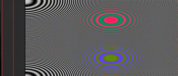
Effect of software PAL decoder on a zoneplate image
It is not so much a case of tayloring the classical "bandwidth" of the filter (for the colour signal is very narrow-band), as obtaining satisfactory edge-response (although for "standard" filters the two are inextricably related... perhaps some kind of non-linear/median filter could be devised???). "Challenging" images include scenes with patchy highly-saturated colour with abrupt boundaries (cross luminance), and fine luminace detail/hard luminance edges (cross colour).
I believe I have optimised my colour-passing filter as far as can be for single-fields. There is still, possibly, scope for improvement of the luminance-passing filter. Of course, some will try to do inter-field (ie frame) filtering... essentially these techniques narrow the filter bandwidth in all 3 dimensions (x,y,time) but will still exhibit artifacts, eg when movement occurs at just the *wrong* speed. If a near-perfect single-frame filter algorithm can be developed, since it makes no inter-field assumptions in the first place, it will not give rise to motion-dependent artifacts.
A Windows 95/98/NT program to decode PAL colour is available for download: palcolor.zip [367kB]
This release can decode single-field PAL, or full-frame NTSC colour pictures. For most standard PAL, you need to set the subcarrier frequency to Fsc=4.43361875MHz, while for the usual NTSC, Fsc=3.579545MHz. You can set an arbitrary rate at which the picture was sampled, and the brightness and colour-saturation can be adjusted. The expected position of the "back porch" (black-level reference) and sub-carrier burst is assumed, based on full 64us scan lines, beginning with the h-sync. For proper display the program requires at least a 32768-colour (15-bit) graphics display setting. The .ZIP archive includes a example PAL-coded capture, img129.bmp, sampled at 15MHz, which can be used to demonstrate the PAL-decoding program.
Extracts from the source code are available on request.

©2001 William Andrew Steer